Introduction
There are many different types of bridges, from simple plank bridges spanning a small stream to elegant suspension bridges supported by tall towers and soaring cables. Other bridges are supported with the structure of the arch, which was used by Roman engineers thousands of years ago. Yet another bridge type is the truss bridge, which gets its strength from a framework of triangles shaped from steel.
Deciding which bridge type to build for a particular location depends on many factors. What type of traffic will cross the bridge? What passes underneath the bridge? What locations are available for foundations for the bridge? How much money is available for building the bridge? What materials are to be used for building the bridge? See the "SuperBridge" website (WGBH, 1997) for an online exercise in picking the correct bridge for a particular site.
In this project, you will do background research to learn about the different types of bridges. In addition to your online and library research, you should also pay attention to the structure of bridges in your area. You will make models of at least three different bridge types, and then test each model to see how much weight it can support. Perhaps you will want to design one or more of your models to resemble a bridge near you.
The main instructions for this project focus on building and testing models made out of popsicle sticks and straws. If you would like to use a computer program to do the modeling and testing, skip to the end of the Procedure.
Terms and Concepts
To do this project, you should do research that enables you to understand the following terms and concepts:
- Strength-to-weight ratio
- Different bridge types:
- Plank
- Arch
- Truss
- Suspension
- Computer Simulation
- Force
More advanced students will also want to study the forces involved:
- Compression
- Tension
- Torsion
- Shear
Questions
- Can you identify the types of the various bridges you encounter in your everyday travels?
- Which bridge type do you think will be the strongest?
- Which bridge type will have the greatest strength-to-weight ratio?
Bibliography
The PBS website "Building Big" has a page on bridges that is a good place to start your background research:
- WGBH Educational Foundation. (2001). "Building Big: All About Bridges," PBS Online. Retrieved August 30, 2012, from http://www.pbs.org/wgbh/buildingbig/bridge/index.html.
On this website, you can learn about different types of bridges (arch, beam, suspension, and cable-stayed), and then play "Build A Bridge." You'll be given a site description, and you have to decide which bridge type would work best there.
Materials and Equipment
This is an engineering project, so the materials you use will depend on your engineering goals. Project kits containing suggested items needed for this science project are available for purchase from AquaPhoenix Education. Make your choice from a kit including a scale or a kit without scale. Alternatively, you can gather the materials yourself using this shopping list:
- Graph paper, for drawing bridge schematics
- Popsicle® sticks (about 60–100 per bridge, depending on the design)
- Wire cutters, for cutting Popsicle sticks
- Elmer's® Carpenter's Wood Glue or Elmer's® Glue-All
- Cotton swabs, for applying wood glue (about 100)
- Binder clips, in both medium and small sizes, for clamping joints on Popsicle stick bridges (12 of each size per bridge; you will need more if you build more than one bridge at a time)
- Plastic straws, straight (about 20–30 per bridge, depending on the design)
- Clear tape, ½ inch width
- Gram balance for weighing bridges, such as the Fast Weigh MS-500-BLK Digital Pocket Scale, 500 by 0.1 G , available at Amazon.com
- Masking tape
- Loading block with hook or eyebolt, for testing bridge strength
- Container for holding bridge load, such as a large bucket
- Rope, ¼ inch to ½ inch diameter (about 3 feet)
- Weights for testing bridge strength (can use metal weights, sand, or water in a container)
- Bathroom scale, for weighing how much weight it takes to break the bridge
The following equipment is optional:
- Camera for before and after photos, and/or
- Video camera for live movie of bridge testing,
- Tripod or helper for video recording.
- Computer (requires Chrome browser) or tablet (Android or iOS) to run Autodesk ForceEffect. This free software can be used to design bridges and to simulate the forces experienced by the bridge's members and joints. You can use this to test out different bridge designs on a computer before you actually build them, or even instead of building them. See the end of the Procedure for more information about the software and how to install it.
Experimental Procedure
Important: the procedure will show you how to build two different bridges with two different materials. However, you cannot make a direct comparison of the strength of these two bridges, because there are too many variables — the bridges are different types and they are made from different materials. This part of the procedure is just intended to introduce you to different ways of building model bridges. For your science project, you will need to build several additional bridges where you only change one variable (for example the bridge material, type of bridge, or joint material), and keep all the other variables constant. Follow the procedure to learn about building model bridges, then see the last step of the procedure for some ideas for the tests you can do.
- Do your background research so that you are knowledgeable about different types of bridges: how they are constructed and the strengths and weaknesses of each type.
- We will show you two different bridges with two different materials: a Warren truss bridge built with Popsicle sticks and a Howe truss bridge built with straws. See Figure 1. We will also show you some tips and tricks for building bridges with Popsicle sticks and straws. After you build these two bridges, you will have the skills you need to build bridges you design yourself.
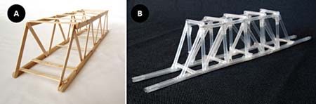
Figure 1. We will show you how to build (A) a Warren truss Popsicle stick bridge and (B) a Howe truss straw bridge.
- Draw a full-scale schematic of your bridge design. Graph paper makes drawing good schematics easier, and a good schematic makes building a bridge much easier. Download schematics for the Warren truss Popsicle stick bridge (pdf) and the Howe truss straw bridge (pdf).
- Aqua Phoenix Kit: The kit includes full-size, 11 by 17 inch printouts of both bridge schematics.
- Construct your models. The schematics for the Popsicle stick and straw bridges you downloaded in step 3 have instructions for making those specific bridges. Lay out the bridge pieces on the schematic you have made or downloaded. The schematic shows you exactly where each piece needs to go. Here are some general tips and tricks to help you as you build bridges.
- Tips for Popsicle Stick Bridges:
- Choose your Popsicle sticks carefully. Look for straight, unbroken, knot-free sticks. Weak Popsicle sticks will make a weak bridge. See Figure 2, for examples of Popsicle sticks to avoid.

Figure 2. Examples of poor-quality Popsicle sticks. Avoid (A) bowed sticks, (B) knotty sticks, (C) bent or curved sticks, and (D) broken sticks. (E) is another example of what knots can look like. - Pay careful attention to glue work at joints. Do not use too much glue—if glue oozes out from between the joint, you have used too much. Wipe off the excess and apply less glue next time. See Figure 3 to see about how much glue to use.
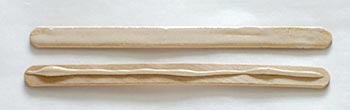
Figure 3. Use a cotton swab to spread a very thin layer of wood glue, as shown on the top stick. Or, apply a thin line of glue down the middle of the stick, as shown on the bottom stick. - After you glue a joint, clamp the joint with a binder clip and keep the binder clip on until the glue in the joint is completely dry. Without clamps, the bond between Popsicles sticks is quite weak. Figures 4, show some different ways to use binder clips as clamps.
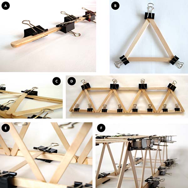
Figure 4. How to use binder clips as clamps. (A) For long, double-thick pieces like top and bottom chords, simply clamp the sticks together every couple of inches. (B) For triangles, clamp the joint at each corner of the triangle. (C) When you attach the triangles to the top and bottom chords, clamp around both the triangle and the chord. (D) Each contact between the chords and triangles needs to be clamped. (E) For attaching top and bottom cross pieces, use a medium binder clip to clamp around the cross piece and chord. Use two clips per cross support, one at each end. (F) Clamp every contact between cross pieces and chords. Remember to let the glue dry completely before removing clamps. - Because you need to let the glue dry completely before removing the clamps, you may find it easiest to build the bridge in steps: assemble the top and bottoms chords, let the glue dry and remove clamps. Then assemble the sides of the bridge, let the glue dry and remove clamps. Finally, add the cross pieces, let the glue dry, and remove clamps.
- It is important that the bridge's sides are parallel to each other and perpendicular to the floor. Otherwise, the load will not be evenly distributed. Before adding cross pieces, use masking tape to tape the two sides of the bridge to boxes, books, or similar objects to hold the sides parallel while you attach the cross pieces. See Figure 5.
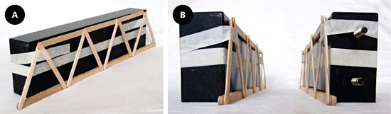
Figure 5. (A) Tape the sides of the bridge to boxes, a stack of books, pieces of wood, or something similar, to keep the sides parallel while you add the cross pieces. (B) Bring the two sides of the bridge together, until they are about a Popsicle stick's length apart. Then add cross pieces. - For the strongest joints, let your finished bridge cure for a day or two before testing it. If you are going to compare the performance of two bridges make sure to let them cure for the same amount of time.
- Choose your Popsicle sticks carefully. Look for straight, unbroken, knot-free sticks. Weak Popsicle sticks will make a weak bridge. See Figure 2, for examples of Popsicle sticks to avoid.
- Tips for Straw Bridges:
- Avoid wrapping tape around the joints so tightly that you bend or deform the straws. See Figure 6 for what you do not want to happen.
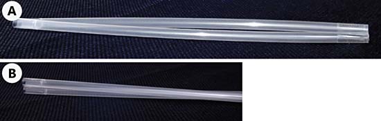
Figure 6. If you tape the straws too tightly, they will deform, which weakens the bridge. (A) The ends of these straws are taped too tightly, so the middle of the straws bow away from each other. (B) These straws were also taped too tightly, so they twisted. You want taped straws to lay flat, without any twisting. - As you assemble larger pieces, like the bridge base and trusses, make sure the pieces lay flat. If you tape them too tightly, the entire base or truss may be twisted. If they twist, your bridge won't be very sturdy. Figure 7 shows what a flat bridge base looks like.
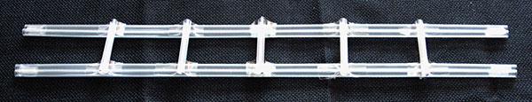
Figure 7. This bridge base lies flat against the ground. This is what you want. If you tape pieces too tightly, then parts of the bridge may not lay flat. - When it comes to connecting straw pieces that are perpendicular to each other, a handy little two-piece taping technique is helpful, as shown in Figure 8.
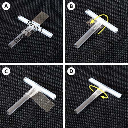
Figure 8. A handy two-piece taping technique. (A) Lay the two pieces perpendicular to each other, with a piece of clear tape placed as shown. (B) Fold the clear tape over Straw 1. (C) Put a second piece of tape Straw 2, near where Straw 2 meets Straw 1. (D) Wrap the second piece of tape around Straw 2. This second piece of tape keeps the first piece of tape from falling off. - The diagonal supports in the truss (see Figure 9) will probably need to be cut to a slightly different length than the ideal length given in the bridge schematic. Cut the supports to whatever length best fits the truss.
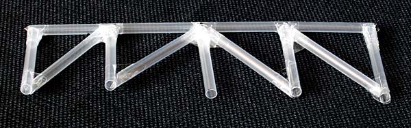
Figure 9. The lengths of the diagonal supports on your bridge truss will probably need to be adjusted from the ideal lengths given in the schematic. Cut the diagonal supports so that they fit from the bottom of a vertical support to the top of a vertical support.
- Avoid wrapping tape around the joints so tightly that you bend or deform the straws. See Figure 6 for what you do not want to happen.
- Tips for Popsicle Stick Bridges:
- Take photographs of each of your model bridges for your display board and lab notebook.
- Weigh each bridge before testing it so that you can calculate the bridge's strength-to-weight ratio after you break the bridge.
- Test how much weight each bridge can bear. Figure 10, shows you how to do this.
- Place the bridge to be tested between two supports (e.g., tables, workbenches, chairs, stacks of books, etc.). The bridge needs to be high enough off the ground to hang a container with weights underneath it. It is best if the container is close to the ground so it does not have far to fall when the bridge collapses.
- Place the loading block on the top, center of the bridge (see Figure 11), and tie a rope from the loading block to the container you will use to load the bridge. In Figure 10, the loading container is a bucket. The bottom of the loading container should be 3 to 6 inches above the floor.
- If you have a video camera, now is the time to start recording!
- Gradually add weight (e.g., metal, sand, or water) to the container. If you use water you may want to put it is in capped bottles to avoid splashing when the bridge breaks.
- Observe the bridge as you gradually add weight, and note any changes that you observe. Add weight until the bridge breaks. Can you identify which part(s) of the bridge failed first? (Video playback can be helpful here, if you have a video camera.)
- When the bridge fails, weigh the container. Record the weight that caused each bridge to collapse.
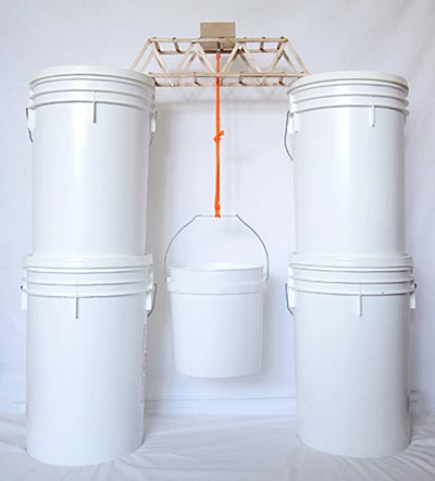
Figure 10. Setup for breaking bridges. Put the bridge between two supports, and center the loading block on top of the bridge. Attach the loading container (a bucket, in this photo) to the loading block. Slowly add weight to the loading container until the bridge breaks.
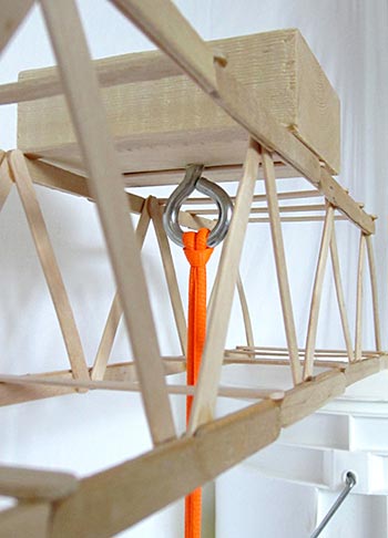
Figure 11. Place the loading block on top of the bridge, in the middle of the bridge. If you make your own loading block, make sure it is slightly wider than your bridge.
- Take photographs of each of your collapsed bridges for your display board.
- Calculate the strength-to-weight ratio of the bridge by dividing the mass it took to break the bridge by the mass of the bridge itself, as shown in Equation 1. Make sure to use the same units for the mass of the load and mass of the bridge.
Equation 1:Strength-to-weight ratio = Mass of load that broke bridge/Mass of bridge - Now that you have built a Warren truss bridge from Popsicle sticks and a Howe truss bridge from straws, it is time to design and test your own bridges. Remember that you should only test one variable at a time, and keep all the other variables constant. For example:
- Build the same type of bridge, one out of popsicle sticks and one out of straws, and compare them.
- Build three different bridge designs, all with popsicle sticks, and compare them.
- Build two copies of the same bridge with popsicle sticks, but use glue for the joints on one bridge and tape for the other bridge.
Optional: Use a Computer to Design Your Bridges
For this project, it is possible for you to build and test several different versions of model bridges. What about engineers who have to design and build real bridges that can be miles long and cost millions of dollars? It would be much too expensive and time-consuming to build and test multiple full-sized versions of the same bridge. So, in addition to building smaller models (like the process described above), engineers also use computer simulations to help them design bridges. These simulations let them predict the forces that will act on different points on a bridge, so they can predict where the bridge is most likely to break.
For this project, you can use simple, free bridge design software called Autodesk ForceEffect to make a simplified two-dimensional design of your bridges (which is like looking at the bridge from a "side view," and assuming the left and right sides are identical—see Figure 12, below). You can then use the program to apply a downward force on the bridge—just like you did in the real experiment by hanging weights from it—and the program will tell you the internal forces in different parts of the bridge. Using this information, you can predict which part of the bridge will break first.

Figure 12. This screenshot of the ForceEffect software shows a simple bridge design with a 100 newton (N) downward force applied at the top (blue). The reaction forces at the bridge's supports are each 50 N (red). The program will also calculate the forces in each individual member of the bridge (for example, the beam between points A and B), so you can predict where the bridge will break based on which beam has the highest forces.
ForceEffect is available on Google Play and in the App Store for Android and iOS devices, respectively. You can also install it on a desktop computer from Google Play as an app in the Chrome browser. To get started using ForceEffect to design and analyze your bridges, watch the following two videos. The first video provides a general introduction to using ForceEffect, and the second video is specifically about designing bridges.
Where do you show the straw bridge being tested
ReplyDeleteRecycled steel trusses promote sustainability without compromising structural integrity or lifespan.
ReplyDeletesquare truss rental orlando