Introduction
The existence of electricity has been known since the ancient Greeks used to rub pieces of amber with fur to make static electricity. Benjamin Franklin is credited with the first demonstration that the electricity in lightning and static electricity are the same in his famous, but very dangerous experiment. It took hundreds of years for thinkers, inventors and scientists to learn how to control and harness the power of electricity.
The first great achievement was the discovery of the concept of a circuit in 1800 by an Italian named Alessandro Volta. He showed that electricity flows through a circuit, and that a circuit needs to be complete, or closed, in order to work. He also invented the first battery, and we use the word Volt to identify the units of electricity.
The first great achievement was the discovery of the concept of a circuit in 1800 by an Italian named Alessandro Volta. He showed that electricity flows through a circuit, and that a circuit needs to be complete, or closed, in order to work. He also invented the first battery, and we use the word Volt to identify the units of electricity.
In 1820, Andr-Marie Ampre published his explanation of Hans Christian Orsted's discovery that magnetic needles could be deflected by an electric current. Ampre's work, later refined by James Clerk Maxwell, firmly established the connection between electricity and magnetism. The movement of electricity through a circuit is called "current", and we measure the current flowing through a circuit in Amperes (often abbreviated "amps").
The next great discovery was by a German school teacher named Georg Simon Ohm in 1826, who had been a student of Volta. He discovered that some materials slowed down, or resisted, the movement of electricity. He found out that there was a relationship between the amount of electricity in a circuit, the movement of electricity through the circuit and the resistance of the circuit. The unit for resistance, Ohms, is named in his honor.
Even though Volta, Ampre and Ohm had paved the way for the first circuits, a real use for electricity still had not been shown and it was mainly a novelty. The first useful invention using electricity was the electric telegraph in 1832, which was used to send messages by code over long distances. But the first practical invention using electricity was the incandescent light bulb by Thomas Edison in 1877.
Electricity is a very important part of our modern world and none of the modern technology we use today could exist without it. All of our modern day gadgets, appliances and electronics use the power of electricity to work. It is the careful balance of parts of a circuit, batteries, wires and resistors; and the completeness of a circuit, which allow electricity to be useful, and not harmful.
In this experiment you will put these pieces together to build your own simple circuit and use it to investigate resistors. What do resistors do, and why are they useful? How will changing the size of the resistor effect the circuit? By varying the size of the resistor, and looking at the effect on a light bulb, we will determine how resistors work in a circuit.
Terms and Concepts
To do this type of experiment you should know what the following terms mean. Have an adult help you search the internet, or take you to your local library to find out more!- electricity
- circuit
- resistor
- current
- conductor
- insulator
Bibliography
Here are some great internet resources available:- Thelwell, A. (2005). The Blobz Guide to Electrical Circuits. Staffordshire University, UK. Retrieved December 13, 2005, from http://www.andythelwell.com/blobz/
- Rader, A. (n.d.). Resisting Current. Physics4Kids.com. Retrieved April 16, 2014, from http://www.physics4kids.com/files/elec_resistance.html
- The Physics Classroom. (n.d.). Current Electricity. Retrieved April 16, 2014, from http://www.physicsclassroom.com/class/circuits
Materials and Equipment
- #2 pencils
- insulated alligator clip set
- 9 V battery
- 9 V battery connector (optional)
- small light bulb rated at 9 V
- small light bulb holder
- ruler
- automatic pencil sharpener
- popsicle stick
- a coping saw (you will need your parents help with this)
Experimental Procedure
Note Before Beginning: This science fair project requires you to hook up one or more devices in an electrical circuit. Basic help can be found in the Electronics Primer. However, if you do not have experience in putting together electrical circuits you may find it helpful to have someone who can answer questions and help you troubleshoot if your project is not working. A science teacher or parent may be a good resource. If you need to find another mentor, try asking a local electrician, electrical engineer, or person whose hobbies involve building things like model airplanes, trains, or cars. You may also need to work your way up to this project by starting with an electronics project that has a lower level of difficulty.
- Set up your circuit board that you will use to test your resistors. You will need three pieces of wire with an alligator clip at each end. You can make your own, or you can buy an insulated alligator clip lead set from a store like Radio Shack.
- Take one wire and attach one end to one terminal of the battery by clipping the alligator clip securely to one of the terminals.
- Attach the other end of that wire to one terminal of the light bulb holder contact screw using the alligator clip.
- Using a new wire, attach one end to the other contact screw of the light bulb holder with the alligator clip.
- Screw the light bulb securely into the light bulb holder.
- Your set up should be similar to the one in this picture:
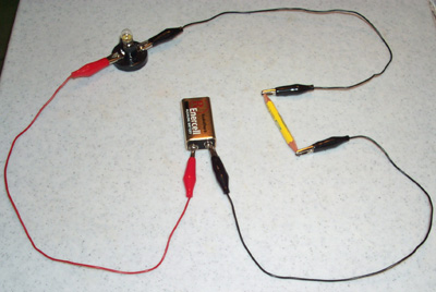
- Before you start your experiment, you need to make sure your circuit works. Touch the two ends of the empty alligator clips to each other, making sure to hold onto the insulated sleeve so you won't get a shock. Does your light turn on? If it does, move on to the next step. If not, go back to step number 1 and check over your circuit to see if everything is connected correctly.
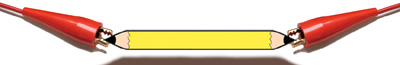
- Next you will make your pencil resistors to test in your circuit. You will be making several different resistors of different sizes by cutting pencils to different lengths and sharpening both ends of the pencil. You will need your parent's help for this part.
- With your parent's help and using a small coping saw, cut the pencils to different lengths. The pencil lengths for this experiment should offer a nice variety of small to large sizes, and be at regular intervals, such as 2 inches, 4 inches, 6 inches, etc...
- After you cut each pencil, use the pencil sharpener to sharpen both ends of the pencil fragment. Don't worry about changing the lengths of your pencils, because you will be measuring them in the next step.
- Use a ruler to measure each piece of pencil from tip to tip of the sharpened pencil lead. Remember to write down and keep a record of your results!
| Length of Pencil: (measured in cm) | ||||||
| Brightness of Light: (off, low, medium, high) |
- Next, place each pencil resistor one at a time into the circuit between the alligator clips by clipping onto the pencil lead portion at the tip of each end of the pencil. It is important to make sure the clips are attached to the graphite and not to the wood, because wood is an insulator and is not a conductive material.
- Look at the light each time you connect one of your pencil resistors to the circuit. Make a record of your observation, and try to use a number scale to describe what you see. For example, you might use a scale of 1 to 5, where 1 is dark and 5 is bright.
- Remember that piece of wire and that wooden popsicle stick? These are your "control" groups. Put them into your circuit and rate them using the same method and scale you used to test your pencils. The extra piece of wire is the "positive control." The popsicle stick is called a "negative control."
yeet
ReplyDelete