Monday 22 June 2015

The Strength of an Electromagnet

Introduction

Electromagnets, or magnets that use the magnetic field created by electrical current flowing through a wire, lie at the heart of many electrical devices, ranging from simple things like doorbells to complex machines, like particle accelerators. The strength of electromagnets varies, but some electromagnets are strong enough to lift entire trains! So how does an electromagnet work? How does electric current—the movement of electric charges—make a magnet?
When electric current flows through a wire, it creates a magnetic field. The magnetic field around a straight wire is not very strong. But if the wire is wrapped in a coil, the fields produced in each turn of the coil add up to create a stronger magnetic field. When the coil is wrapped in the shape of a cylinder, it is called a solenoid. (See Figure 1).
Magnetic field lines of a magnetic coil.
Electronics Science science project
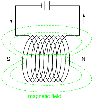
Figure 1. The green lines show the magnetic field surrounding a solenoid (or cylindrical coil) through which electric current is flowing. "N" and "S" indicate the north and south poles of the electromagnet.
If an electromagnet consists only of coiled wire (if it has nothing but air in its middle) then the magnet will not be very strong. But if you place a piece of iron in the middle of the coil—an iron bolt, for example—then the piece of iron, called the magnetic core or iron core of the electromagnet, will make the magnetic field much stronger (see Figure 2). This is because iron is ferromagnetic. It contains lots of tiny areas, called magnetic domains, that act like small magnets. As soon as the iron core is placed in the coil, the magnetic domains line up with the magnetic field made by the coiled wire solenoid. As a result, the strength of the magnetic field around the solenoid greatly increases.
Electromagnet science fair project: diagram of an electromagnet
Electronics Science science project
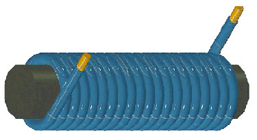
Figure 2. Insulated wire (blue) wrapped around an iron core (black). Electric current flowing through the wire creates a magnetic field, a field that is magnified by the iron core.
In this science project, you will investigate how the strength of the magnetic field produced by an electromagnet changes as the number of turns in the coil increases.

Terms and Concepts

To do this project, you should do research that enables you to understand the following terms and concepts:
  • Electromagnet
  • Electric current
  • Solenoid
  • Iron core
  • Ferromagnetic
  • Magnetic domains

Questions

  • How does an electromagnet work?
  • Why does an electromagnet have magnetic properties only when energized?
  • Does increasing the current flowing through a coil of wire increase or decrease the strength of the magnetic field?
  • What does adding an iron core to an electromagnet do to the magnetic field created by the electromagnet?

Materials and Equipment 

  • The Strength of an Electromagnet kit (1). Includes:
    • 6 volt (V) lantern battery
    • Enamel-coated magnet wire, 30 AWG (75 feet)
    • Alligator clip leads (2)
    • Iron bolts; about 2 ½ inches long and ½ inch in diameter (4)
You will also need to gather these items, not included in the kit:
  • 220 grit sandpaper (about 1 square inch)
  • Masking tape (1 roll)
  • Box of steel paper clips (about 100 count)
  • Scissors or wire cutters
  • Optional: shallow plastic container, slightly longer and wider than the iron bolts

Experimental Procedure

  1. Make four different electromagnets, with 50, 100, 150, and 200 turns of wire respectively, by wrapping the magnet wire tightly around the iron bolts. See Figures 3 and 4 for example electro magnates. It is important to wrap the magnet wire neatly around the bolts. Here are some tips to make wrapping easier (if you run into trouble doing the experiment, see the FAQ for more information):
    1. Leave a tail of wire (5-6 centimeters [cm] long) at each end of the coil. You will use these wire tails to connect the coil to the battery.
    2. Make a holder for the spool of magnet wire, so you can roll the wire right off the spool. For example, you can stick a pen or pencil through the spool, and tape the pencil to a couple of small boxes.
      1. Use a small piece of masking tape to attach the wire to the iron bolt, near where the head of the bolt connects to the shaft of the bolt.
      2. Turn the iron bolt to unwind the magnet wire from the spool. Use your fingers to keep the wire tight against the bolt. Wrap each successive turn so that the wire lines up neatly. Remember that it is important to wind the wire tightly and neatly.
      3. Keep track of how many turns you make (or how many times you wrap the wire around the bolt). A turn happens each time the tape that holds the wire in place comes around. Counting turns is easier if you can recruit a helper to make tally marks for you.
        1. Troubleshooting Tip: If you are having trouble keeping track of how many turns you have made, here are two tips.
          • First, draw a line straight down the iron core using a permanent marker. Count one turn each time you pass that line.
          • Second, if you know the gauge of your magnet wire, you can look up the diameter of the wire in a table, like this one for American wire gauge. Once you know the wire's diameter, you can calculate how much of the bolt should be covered by a given number of coils. That means that 100 turns cover 1 inch of the bolt (0.01 inches x 100 = 1 inch), if the turns are right next to each other and do not overlap. So, if you wrap your coil very neatly, you can get a rough idea of how many turns are in your coil by measuring how much of the bolt is covered by the coil. Note that this method does not work if your coil has more than one layer of wire or if there are spaces between turns.
      4. When you reach the desired number of turns, tape the wire to the bolt to hold the coil in place. Cut the wire, leaving a 5-6 cm long "tail" for making the connection to the battery.
      5. Particularly for larger coils, you may need to wrap multiple layers of wire, one layer on the other, to get the desired number of turns.
    3. Use the 220 grit sandpaper to sand off 1 cm of the enamel insulation from the end of each magnet wire tail. Wire Stripping Tutorial for an instructional video that shows how to strip magnet wire.
      1. Fold a small piece of sandpaper (about the size of two postages stamps, use scissors to cut a small piece of necessary) in half, with the rough sides facing each other, to make a "sandpaper sandwich".
      2. Put the end of the magnet wire to be stripped inside the sandpaper sandwich.
      3. While softly pressing the sandpaper sandwich together, gently pull the wire through the sandpaper sandwich, turning the wire as you pull so that you remove the insulation from all sides of the wire. Or, you can rub the wire back and forth inside the sandpaper sandwich.
      4. The wire is stripped when you can see the shiny copper wire underneath.
        1. Troubleshooting Tip: It is a good idea to practice stripping the enamel insulation off a practice piece of wire. You may need some practice to get the pressure right so that the wire does not break while you sand it.
    4. Place the paper clips in a shallow container (slightly longer and wider than the electromagnet). If you do not have a shallow container, put the paperclips in a pile on a flat surface.
    5. Starting with the 50-turn coil, use the electromagnet to pick up paper clips from the shallow container.
      1. Use the alligator clip leads to connect the coil to the battery. When current flows through the coil, the coil is energized and will behave as a magnet. When no current flows through the coil, the magnetic characteristics of the electromagnet disappear.
        1. Troubleshooting Tip: After connecting the coil to the battery, you can check that the electromagnet works by touching a paper clip to the coil. If the paper clip sticks, then the electromagnet is working. If the paper clip does not stick, then the electromagnet is not working. If this is the case, make sure that the alligator clips are connected to both the battery and the wire. One end of each lead should be clipped to one of the terminals of the battery (one lead to each terminal), and the other end of each of lead should be clipped to the stripped part of the magnet wire (one lead to each end of the wire). If the clip leads are connected correctly to the coil and battery but the electromagnet is still not working, then the problem may be that the magnet wire was not completely stripped. Try re-sanding the ends of the magnet wire until all of the reddish insulation is gone, then reconnect and retest the electromagnet.
      2. Touch the energized coil (lengthwise) to the paper clips, and then pull the coil away from the tray. See Figures 3 and 4.
        Electromagnet science fair project idea: electromagnet picking up objects
Electronics Science science project
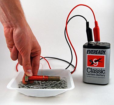
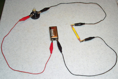
        Figure 3. After connecting the alligator clip leads to the battery and wire on the coil, the electromagnet will be energized. Lower the electromagnet into the container of paper clips so that the long part of the electromagnet touches the paper clips.

        Electromagnet physics electricity science fair project idea: electromagnet with paper clips
Electronics Science science project
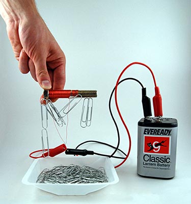
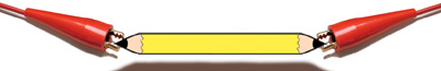
        Figure 4. Once you have touched the electromagnet to the paper clips, lift the electromagnet up. Some of the paper clips will stick to the electromagnet. Move the electromagnet away from the container (so that the paper clips will not fall back into the container) and then disconnect the coil from the battery.
      3. Once the coil is no longer over the container, disconnect the coil from the battery, and count how many paper clips the coil picked up. Record the number in your lab notebook. Organize your data in a table like Table 1.
      4. Repeat steps 4a to 4c four more times, for a total of five trials.
    6. Repeat step 4 for the 100-, 150-, and 200-turn coils.
    7. Calculate the average number of paper clips lifted by each coil (see Table 1).
    Number of Turns on CoilsNumber of Paper Clips Picked Up
    12345Average
    50
    100
    150
    200
    Table 1. Record the number of paper clips each coil picked up in each of the five trials and then calculate the average for the five trials.

    Analyzing the Data

    1. Make a graph of the results. Plot the number of paper clips picked up (y-axis) versus the number of turns in the coil (x-axis). If you need help making a graph, try using the Create a Graph website.
    2. Does the number of paper clips picked up by the coil increase or decrease as you increase the number of turns in the electromagnet?

    Friday 12 June 2015

    Rock On! Recording Digital Data with Magnets

    Introduction

    Today, magnetic disk drives are used to store and retrieve information for many different applications. Digital video recorders (DVRs), MP3 players, cell phones, and gaming systems are all examples of popular products that use a disk drive to store and retrieve information. Some other applications that you may not be familiar with are global positioning systems (GPS), banking systems, and cars.
    How are all these different kinds of information stored on magnetic disk drives? How much data can fit in a given amount of space on a disk? How is data erased from a disk? This project will help you answer these questions as you learn how magnetic materials are used to store information.
    Information like words, music, pictures, or movies is translated into a format that can be saved onto various permanent storage devices, like a magnetic disk drive. This translation is called digitization, which means that the information is converted into a stream of numbers. The smallest unit for digital information is called a bit. A bit can be either 0 or 1, that's it. By stringing together a series of bits, larger numbers can be represented. For example, a byte is a sequence of 8 bits. A byte can encode 28 (= 256) unique values. 

    Letters, numbers, and other symbols for printed text are digitized using a standard code, called ASCII (ASCII is an acronym for American Standard Code for Information Interchange). Using the ASCII table, what sequence of bits would correspond to the word "digitize?"

    In this project, you will digitize a short piece of text (e.g., the name of your favorite band) using the ASCII representation of the text. Next, you will use bar magnets to represent the individual bits of the digitized text. The orientation of the magnet will determine whether it represents a 0 or a 1. You'll see how close together your magnets can be packed while still preserving your stored information. Finally, you'll see how easily you can erase your stored information with a permanent magnet. 

    Terms and Concepts
    To do this project, you should do research that enables you to understand the following terms and concepts:
    • Bit
    • Byte
    • ASCII

    Questions

    • Before MP3 players and DVRs, what was used to store and retrieve music and video?
    • What are other examples of storage and retrieval methods or systems?
    • Why do you think disk drives devices like iPODs and DVRs have replaced tape-based devices like Walkmans and VCRs?

    Materials and Equipment

    A project kit containing most of the items needed for this science project is available for purchase from AquaPhoenix Education. Alternatively, you can gather the materials yourself using this shopping list:
    • A print-out of the ASCII code and binary code of the alphabet
    • Bar magnets, 1-inch (24); North and South poles must be marked
    • Horseshoe magnet, large (1); a 8-inch magnet is recommended
    • Paper
    • Tape; scotch tape works well but any kind of tape will do.
    • Ruler or measuring tape
    • Lab notebook

    Experimental Procedure

    In this experiment, you will digitize a short piece of text (any 3-letter name or word you want) using the ASCII representation of the text. Next, you will use bar magnets to represent the individual bits of the digitized text. The orientation of the magnet will determine whether it represents a 0 or a 1. You will see how close together your magnets can be packed while still preserving your stored information. Finally, you will see how easily you can erase your stored information with a permanent magnet.
    1. You will need a three letter word, name, or acronym to digitize. It can be anything you want.
    2. Make a table, in your lab notebook, to translate your chosen word or phrase into the binary ASCII code. 
    Jem
    0100 10100110 01010110 1101
    1. Now use individual bar magnets to represent each bit of the coded word.
      1. Tape several pieces of paper together lengthwise. Using your ruler to measure, draw 24 rectangles. Each rectangle should be 2 inches long (left to right) and 1 inch wide (up and down).
      2. We will say that a magnet with its N pole facing right is a 1, and a magnet with its N pole facing left is a 0 as shown below in Figure 1. (To make your code easier to see, you may want to color the N half of each magnet.) Place one magnet in each rectangle on your paper, arranging them according to the binary code for your word or phrase.
    2. What is the information density of your recording? How many bits per square inch? Record your calculation in your lab notebook. Just for comparison, a 1990 hard disk could store 1 billion (1,000,000,000) bits per square inch, and a 2006 hard disk can store 100 billion (100,000,000,000) bits per square inch.
      1. Square inches are calculated by multiplying the number of rectangles on your paper by the length of each rectangle by the width of the each rectangle. For example, 24 rectangles x 2 inches length x 1 inch width = 48 square inches.
      2. Every 1/0 is a bit. Since every 1/0 is represented by a magnet you can count the total number of magnets in order to calculate the number of bits.
      3. Bits per square inch is the total number of bits divided by the total square inches.
    a magnet where the N is on the right a '0' and a magnet where the N is on the left a '1'.
Electricity Electronics science project
    Figure 1. For this project, we will call a magnet where the N is on the right a "0" and a magnet where the N is on the left a "1".
    1. Gently jiggle your paper. What happens to the arrangement? Are some of the magnets attracted (or repelled) by their neighbors? Did something like this happen to your magnets (see Figure 2)?
    Neighboring bar magnets with opposite polarity are attracted to one another when tray is tapped.
Electricity Electronics science project
    Figure 2. Neighboring bar magnets with opposite polarity are attracted to one another when paper is jiggled.
    1. If the magnetic material on a recording surface could move around like your bar magnets, how do you think this would affect the durability of the recording?
    2. Create a new set of rectangles, on paper, for your magnets. Keep the width 1 inch and decrease the length of the rectangle to 1 ¾ inches. What is the information density now? Do the magnets interact with their neighbors (without you jiggling the paper) or stay separated?
    3. Repeat step 7 with increasingly smaller length rectangles. Each time, decrease the length of the rectangle by ¼ inch and record your calculations and observations in your lab notebook. How small can your squares be without the magnets interacting with their neighbors? What is the highest recording density (in bits per square inch) you can achieve?
    4. Once you have found the highest recording density possible with your bar magnets, arrange the magnets on your paper again using that rectangle size. Take the horseshoe magnet and, holding it a foot above the paper (measure with the ruler), pass it over the bar magnets. Did any of the bar magnets move?
      1. If the bar magnets did not move, lower the horseshoe magnet slightly and try again. At what height does the horseshoe magnet move the bar magnets?
      2. If the bar magnets did move, raise the horseshoe magnet slightly and try again. At what height does the horseshoe magnet first stop moving the bar magnets?
      3. Record your observations in your lab notebook.
      4. What does this tell you about erasing data stored on magnetic recording media? Would it be okay to put a strong magnet next to an iPad, computer, or cell phone?

    Monday 8 June 2015

    Which Materials are the Best Conductors?

    Introduction

    The existence of electricity has been known since the ancient Greeks used to rub pieces of amber with fur to make static electricity. Benjamin Franklin is credited with the first demonstration that the electricity in lightening and static electricity are the same in his famous, but very dangerous, experiment. It took hundreds of years for thinkers, inventors and scientists to learn how to control and harness the power of electricity. 

    The first great achievement was the discovery of the concept of a circuit in 1800 by an Italian named Alessandro Volta. He showed that electricity flows through a circuit, and that a circuit needs to be complete, or closed, in order to work. He also invented the first battery, and we use the word Volt to identify the units of electricity.
    The next great discovery was by a German school teacher named Georg Simon Ohm in 1826, who had been a student of Volta. He discovered that some materials slowed down, or resisted, the movement of electricity. He found out that there was a relationship between the amount of electricity in a circuit, the movement of electricity through the circuit and the resistance of the circuit. The movement of electricity through a circuit is described by Ohm's Law, which relates the voltage (measured in volts, abbreviated V) to the current (measured in amperes, abbreviated A) and to the resistance (measured in ohms, abbreviated with a capital Greek letter omega: Ω).
    Electricity flows very well through some materials, and not so well through others. Materials that allow electricity to flow freely are called conductive materials. Materials that make the flow of electricity difficult are called insulators. Conductive materials have a very low resistance, and insulators have a very high resistance. Both conductors and insulators are common materials used to build circuits. The most common example is a copper wire (a conductor) that is covered by a plastic coating (insulator) used to make a circuit.
    What other types of materials are conductors and insulators? In this experiment you will build your own simple light bulb circuit and use it to test different materials to see if they are conductors or insulators. By putting different materials in the circuit and observing the brightness of the bulb, you can make a list of conductors and insulators.

    Terms and Concepts

    To do this type of experiment you should know what the following terms mean. Have an adult help you search the Internet, or take you to your local library to find out more!
    • electricity
    • circuit
    • electrons
    • current
    • resistance
    • conductor
    • insulator
    Questions
    • How do electrons flow through different materials?
    • How is resistance measured?
    • How can different materials be tested for conductivity?

    Bibliography

    Here are some great Internet resources available:
    • Surf this website for kids by the First Energy Corporation. Find out about electricity, history, efficiency and safety while having fun too! They also provide an excellent glossary:
      First Energy Corp., 2005. "Electric Avenue." Akron, OH. [12/13/05] http://www.firstenergycorp.com/kids/
    • Thelwell, A., 2005. "The Blobz Guide to Electrical Circuits." Staffordshire University, UK. [12/13/05] http://www.andythelwell.com/blobz/
    • The best place to buy parts for exploring and playing with electricity will probably always be Radio Shack. Find all of your supplies on the online catalog:
      Radio Shack Corp., 2005. "Cables, Parts & Connectors" Fort Worth, TX. [12/13/05] http://www.radioshack.com/category/index.jsp?categoryId=2032058
    • This site has a java applet you can use to make printable, color graphs of your data:
      NCES, 2006. "Create a Graph," National Center for Education Statistics (NCES) U.S. Dept. of Education. [accessed: 3/3/06 ]http://nces.ed.gov/nceskids/createagraph/

    Materials and Equipment

    To do this experiment you will need:
    • several small pieces of different materials to test (aluminum foil, paper clips, wood, plastic, rubber bands, string, etc...);
    • 6 V battery (e.g., Radio Shack 23-560);
    • 3 wire leads with alligator clips at both ends (e.g., Radio Shack 278-1156; they can be any color, but to tell them apart we will call them 'red,' 'black,' and 'yellow');
    • 6 V light bulb with wire leads (e.g., Radio Shack 272-1140);
    • flat, insulating surface (like a cutting board).

    Experimental Procedure

    1. Set up your circuit board that you will use to test your materials. You will need three pieces of wire with an alligator clip at each end. You can make your own, or you can buy an insulated alligator clip lead set from a store like Radio Shack.
    2. Attach one clip of the black wire to the (−) battery terminal by clipping the alligator clip securely to the terminal.
    3. Attach one clip of the red wire to the (+) battery terminal by clipping the alligator clip securely to the terminal.
    4. Attach the other end of the black wire to one of the light bulb leads.
    5. Attach the one clip of the yellow wire to the other light bulb lead.
    6. You will connect your different materials between the free ends of the red wire and the yellow wire.
    7. Make a data table for your results, including a place to write the type of material, source of material and the brightness of the light bulb:
      Type of MaterialSource of MaterialBrightness of Bulb
      (e.g., off, dim, bright)


    8. Next, place the first material into the circuit by clipping one end to the free red clip and the other end to the free yellow clip.
    9. Does the light bulb light up? How bright is it? Write down the results in the data table.
    10. Repeat steps 8 and 9 for each different material you want to test. Remember to write down, in your data table, how bright the light bulb appears for each material you test.
    11. How do the different materials compare? Do some materials have make the light bulb glow brightly while others only make it glow dimly? Do some materials not make the light bulb light at all?
    12. Categorize the materials according to your results. Put materials with high brightness readings (high brightness = high conductivity = low resistance) into the conductor category. Put materials with 'dim' brightness readings into the 'poor conductor' category. Put materials with 'off' brightness readings (no brightness = high resistance = low conductivity) into the insulator category.
      InsulatorsPoor ConductorsConductors


    Electric Play Dough Project 2: Rig Your Creations With Lots of Lights!

    Introduction

    In Project 1 of our "Electric Play Dough" science project series, "Make Your Play Dough Light Up, Buzz, & Move!", you learned about the basic ideas of closed,open, and short circuits. If you need to review this information, you can always go back to the Make Your Play Dough Light Up, Buzz, & Move! Introduction section.

    In Project 1, you only learned how to hook up one light to your creation. Imagine how cool your creations can be if you hook up lots of lights! This science project will show you how!
    In order to do this, first you will need to learn about two new kinds of circuits. The examples will explain a circuit that has one battery and three light bulbs. There are different ways to connect multiple light bulbs to a battery: in "series" or in "parallel." We will explain what these words mean next.
    In a series circuit, the lightbulbs are all connected in a row, and form a single loop. The path the electricity takes from the positive end of the battery to the negative end has to go through each lightbulb. This is shown in Figure 1.
    series circuit with battery and lightbulbs
    Figure 1. Three lightbulbs connected to a battery in series. Notice how there is only a single "loop," and the path that the electricity takes (represented by the yellow arrows) has to go through each lightbulb in order.
    In a parallel circuit, the lightbulbs are connected next to each other, and form multiple loops. Any path electricity takes to get from the positive end of the battery to the negative end only goes through one light bulb. This is shown in Figure 2.
    parallel circuit with battery and lightbulbs
    Figure 2. Three lightbulbs connected to a battery in parallel. Notice how there are multiple "loops," and any path the electricity takes (represented by the yellow arrows) only goes through one light bulb.
    One important thing to know is that the shape the wires connecting the lightbulbs makes does not matter. In other words, you can move the light bulbs and wires around, but as long as the connections stay the same, you will not change if a circuit is series or parallel. Look at Figures 3 and 4; the light bulbs have been moved around (and the shapes the wires make have changed), but they are still the same kind of circuit as Figures 1 and 2.
    rearranged series circuit with battery and lightbulbs
    Figure 3. The lightbulbs in this figure have been rearranged relative to those in Figure 1. However, there is still only one path for the electricity to take, which goes through all three lightbulbs, so this is still a series circuit!

    parallel circuit with battery and lightbulbs
    Figure 4. The lightbulbs in this figure have been rearranged relative to those in Figure 2. However, there are still multiple paths for the electricity to take, and each path only goes through one light bulb, so this is still a parallel circuit!
    So, now that you know the difference between series and parallel circuits, it is time to apply this knowledge to your squishy circuits! First let us see what happens when we try hooking up first one, then two, then three LEDs (light-emitting diodes, which are a type of tiny lightbulb found in many electronic devices) in series using squishy circuits. This is shown in Figure 5.
    squishy circuits with one, two, three LEDs in series
    Figure 5. (From left) One, two, and then three LEDs connected to the battery pack in series using squishy circuits. The LEDs get much dimmer as each new LED is connected.
    Uh-oh! Do you see a problem in Figure 5? The LEDs get dimmer each time a new LED is plugged in. With only three LEDs, you can barely see them light up at all! This is certainly going to be a problem if you want to hook up lots of lights to your creation. So, let us find out what happens if we connect the three LEDs in parallel instead. This is shown in Figure 6.
    squishy circuits with one, two, three LEDs in parallel
    Figure 6. (From left) One, two, and then three LEDs connected to the battery pack in parallel using squishy circuits. Each new LED is just as bright as the previous one.
    That is much better! In Figure 6, all the LEDs are the same brightness. This means that when you hook lots of lights up to whatever you build, you need to connect them in parallel. Now, why does this happen? Because in a series circuit, some electricity is "lost" each time it goes through an LED. So, by the time the electricity has already gone through one or two LEDs, there is not enough energy left to power the rest of them. In a parallel circuit, the electricity goes straight from the battery to each LED without losing energy first. This allows you to light up more LEDs (you'll find a more detailed explanation in the Technical Note section below, but only if you are curious; you do not need to understand that information to do this science project).
    One more important thing to note: even in parallel, your LEDs will start to get dimmer if you make a very big structure or have very long sections of conductive play dough, and use lots of LEDs. This is because some electricity is lost as it flows through the conductive dough, and there is a limited amount of electricity that the batteries can supply. You can see this in Figure 7; the LEDs that are closer to the battery wires are brighter than the ones that are far away.
    squishy circuit with ten LEDs in parallel
    Figure 7. All ten of these LEDs are connected in parallel. The electricity does not have to travel as far to get to the LEDs that are closer to the battery pack, so those LEDs are brighter. The LEDs on the far right are dimmer because the electricity has to travel much farther to get to them.
    Now that you are an expert on series and parallel circuits, you are ready to start making designs with lots of lights!
    Technical Note
    You may be wondering why the LEDs stay bright when you connect three of them in parallel, but barely light at all when you connect three in series. After all, you are connecting the same three lights to the same battery pack; shouldn't they be the same brightness either way?
    It turns out this is because of how voltage works in series and parallel circuits. The battery pack uses four AA batteries, and supplies 6 volts (abbreviated as V). Each LED requires a "voltage drop" of about 2.5 V to fully light up. So, if you connect three LEDs in series, that is 3 x 2.5 = 7.5, which is more voltage than the battery pack can supply! This is why the LEDs are so dim. However, if you connect three LEDs in parallel, they are each connected directly to the positive and negative terminals of the battery, with the full 6 V available to power each one of them. So, you can attach many more LEDs in parallel and they will remain at full brightness.

    Terms and Concepts

    • Closed circuit
    • Open circuit
    • Short circuit
    • Series circuit
    • Parallel circuit
    • Voltage

    Questions

    • What is the difference between a series and a parallel circuit?
    • Can you draw your own series and parallel circuits, each with four light bulbs?
    • Which type of circuit is better for hooking up multiple LEDs in your squishy circuit: series or parallel?

    Bibliography

    The developers of Squishy Circuits have a helpful reference on series and parallel circuits:

    Materials and Equipment 

    Note: if you have already purchased a Squishy Circuits Kit and the materials to make conductive and insulating play dough for a previous squishy circuits science project, you can reuse those materials and do not need to buy new supplies..
    • Squishy Circuits kit (1). Includes:
      • DC hobby motor
      • Piezoelectric buzzer
      • Mechanical buzzer
      • 4 AA Battery pack
      • Jumbo LEDs (25 total — 5 each in red, green, white, yellow, and blue)
      • Conductive play dough recipe
      • Insulating play dough recipe
    You will also need to gather these items:
    • AA batteries (4)
    • Mixing bowl
    • Measuring cups
    • Measuring spoons
    • Spoon or spatula
    • Pot you can use on the stove
    • Adult helper
    • Ingredients to make conductive and insulating play dough
      • Tap water (1 C.)
      • Deionized or distilled water (1/2 C.); deionized or distilled water is available in the bottled water section of most grocery stores
      • Vegetable oil (4 tbsp.)
      • Cream of tartar (3 tbsp.; note that a 1.5 oz jar is the same as 3 tbsp.) or lemon juice (9 tbsp.)
      • Flour (3 C.)
      • Salt (1/4 C.)
      • Sugar (1/2 C.)
      • Optional, but highly recommended: Food coloring
    • Plastic bags or containers in which to store play dough so it does not dry out

    Experimental Procedure

    Making the Electric Play Dough

    Follow the directions in your Squishy Circuits Kit to make conductive and insulating play dough. The directions are written on the inside of the lid of your Squishy Circuits Kit, and we have reproduced them here for convenience. You can also watch videos, below, of how the conductive and insulating play doughs are made.Important: Ask an adult to help you use the stove to make the play doughs.

    Conductive Play Dough

    StepIngredientsProcedure
    11 cup (C.) water
    1 C. flour
    ¼ C. salt
    3 tablespoons (tbsp.) cream of tartar or 9 tbsp. lemon juice
    1 tbsp. vegetable oil
    Optional: food coloring (a few drops)
    • Mix all the ingredients in a clean mixing bowl.
    • Note that you are only including 1 C. of flour for now.
    2None in this step.
    • Transfer the mixture to a pot.
    • Stir the mixture from step 1 continuously over medium heat until a dough ball forms.
    3½ C. flour
    • Turn off the stove. Carefully remove the pot from the heat and dump the play dough back into your mixing bowl.
    • Wait several minutes for the mixture to cool. Once it has cooled down, knead (mix the dough with your hands) in additional flour until desired consistency is formed.
    Table 1. Directions for making conductive play dough.
    This video is a step-by-step tutorial on making the conductive play dough. It should help answer any questions you have about how to judge the consistency of your play dough at each step.

    Insulating Play Dough

    Important: We found that adding the full ½ C. of distilled water to the insulating dough in step 2 was too much (the dough became too sticky). Be sure to add small amounts of water slowly as you stir, and stop when the dough has reached a good consistency.
    StepIngredientsProcedure
    11 C. flour
    ½ C. sugar
    3 tbsp. vegetable oil
    • Mix all the ingredients in a clean mixing bowl (especially if you used food coloring to make your conductive play dough).
    • Note that you are only including 1 C. of flour for now.
    2½ C. deionized or distilled water
    • Slowly add small amounts of water as you continuously knead the dough.
    • Do not add the whole 1/2 C. of water at once or your play dough may become too sticky. You might not need to use the whole ½ C.
    3½ C. flour
    • After a dough ball has formed, knead in additional flour to remove stickiness.
    Table 2. Directions for making insulating play dough.
    This video is a step-by-step tutorial on making the insulating play dough. It should help answer any questions you have about how to judge the consistency of your play dough at each step.

    Building Electric Play Dough Circuits

    1. Insert the four AA batteries into the battery pack that came with your Squishy Circuits Kit.
    2. First, do an experiment to see how many LEDs you can connect in series.
      1. Start by connecting one LED to the battery pack using conductive play dough. Remember from Project 1 in our "Electric Play Dough" science project series that you should use insulating play dough between the conductive play dough pieces to prevent short circuits between the LED leads.
      2. Now, add a second LED in series, like in Figure 5 from the Introduction. Do the LEDs get dimmer?
      3. Add a third LED in series. Do they get even dimmer?
      4. Continue this process until the LEDs do not visibly light up at all.
    3. Now, do an experiment to see how many LEDs you can connect in parallel.
      1. Start by connecting one LED to the battery pack using conductive play dough. Remember from Project 1 that you should use insulating play dough between the conductive play dough pieces to prevent short circuits between the LED leads.
      2. Now, add a second LED in parallel, like in Figure 6 from the Introduction. Do the LEDs get dimmer?
      3. Add a third LED in parallel. Do they get dimmer?
      4. Continue to add LEDs in parallel. Do they eventually get dimmer? Can you make them brighter by keeping them very close together?
    4. What happens if you add a buzzer or a motor with the lights? Can you power more than one buzzer? How many lights can you put in series and still get sound out of the buzzer? How about the in parallel? Make a table with your results. Based on your findings which takes the most power, an LED, one of the buzzers, or the motor?
    5. Now, plan out the shape that you want to make (drawing it is a good idea) and how you want to add lights. Remember that if you want to use a lot of LEDs, you will need to connect them in parallel, and that the actual shape of the play dough does not matter, as long as each LED has its own "loop" formed with the battery. You might need to use insulating play dough in some places to prevent a short circuit. Figure 8, below, shows two design examples.
    6. Build your shape and start adding lights! Remember from Project 1 that LEDs only work in one direction (the longer lead should be connected to the positive side of the battery pack, with the red wire), so if one does not light up, try flipping it around. If your circuit is not lighting up at all, make sure you remembered to turn your battery pack on, and that you do not have a short circuit somewhere. If you are still having trouble, you can refer to our FAQ section.
    squishy circuits smiley face with LEDs in parallel
    Figure 8. Two design examples: (left) a ring of LEDs, and (right) a smiley face. Notice how both circuits use an "inner ring" and an "outer ring" to connect the LEDs to the battery pack wires, as well as some insulating play dough to let one of the wires access the inner ring without touching the outer ring (which would create a short circuit).

    Pencil Resistors

    Introduction

    The existence of electricity has been known since the ancient Greeks used to rub pieces of amber with fur to make static electricity. Benjamin Franklin is credited with the first demonstration that the electricity in lightning and static electricity are the same in his famous, but very dangerous experiment. It took hundreds of years for thinkers, inventors and scientists to learn how to control and harness the power of electricity.

    The first great achievement was the discovery of the concept of a circuit in 1800 by an Italian named Alessandro Volta. He showed that electricity flows through a circuit, and that a circuit needs to be complete, or closed, in order to work. He also invented the first battery, and we use the word Volt to identify the units of electricity.
    In 1820, Andr-Marie Ampre published his explanation of Hans Christian Orsted's discovery that magnetic needles could be deflected by an electric current. Ampre's work, later refined by James Clerk Maxwell, firmly established the connection between electricity and magnetism. The movement of electricity through a circuit is called "current", and we measure the current flowing through a circuit in Amperes (often abbreviated "amps").
    The next great discovery was by a German school teacher named Georg Simon Ohm in 1826, who had been a student of Volta. He discovered that some materials slowed down, or resisted, the movement of electricity. He found out that there was a relationship between the amount of electricity in a circuit, the movement of electricity through the circuit and the resistance of the circuit. The unit for resistance, Ohms, is named in his honor.
    Even though Volta, Ampre and Ohm had paved the way for the first circuits, a real use for electricity still had not been shown and it was mainly a novelty. The first useful invention using electricity was the electric telegraph in 1832, which was used to send messages by code over long distances. But the first practical invention using electricity was the incandescent light bulb by Thomas Edison in 1877.
    Electricity is a very important part of our modern world and none of the modern technology we use today could exist without it. All of our modern day gadgets, appliances and electronics use the power of electricity to work. It is the careful balance of parts of a circuit, batteries, wires and resistors; and the completeness of a circuit, which allow electricity to be useful, and not harmful.
    In this experiment you will put these pieces together to build your own simple circuit and use it to investigate resistors. What do resistors do, and why are they useful? How will changing the size of the resistor effect the circuit? By varying the size of the resistor, and looking at the effect on a light bulb, we will determine how resistors work in a circuit.

    Terms and Concepts

    To do this type of experiment you should know what the following terms mean. Have an adult help you search the internet, or take you to your local library to find out more!
    • electricity
    • circuit
    • resistor
    • current
    • conductor
    • insulator

    Bibliography

    Here are some great internet resources available:

    Materials and Equipment

    • #2 pencils
    • insulated alligator clip set
    • 9 V battery
    • 9 V battery connector (optional)
    • small light bulb rated at 9 V
    • small light bulb holder
    • ruler
    • automatic pencil sharpener
    • popsicle stick
    • a coping saw (you will need your parents help with this)

    Experimental Procedure

    Note Before Beginning: This science fair project requires you to hook up one or more devices in an electrical circuit. Basic help can be found in the Electronics Primer. However, if you do not have experience in putting together electrical circuits you may find it helpful to have someone who can answer questions and help you troubleshoot if your project is not working. A science teacher or parent may be a good resource. If you need to find another mentor, try asking a local electrician, electrical engineer, or person whose hobbies involve building things like model airplanes, trains, or cars. You may also need to work your way up to this project by starting with an electronics project that has a lower level of difficulty.
    1. Set up your circuit board that you will use to test your resistors. You will need three pieces of wire with an alligator clip at each end. You can make your own, or you can buy an insulated alligator clip lead set from a store like Radio Shack.
    2. Take one wire and attach one end to one terminal of the battery by clipping the alligator clip securely to one of the terminals.
    3. Attach the other end of that wire to one terminal of the light bulb holder contact screw using the alligator clip.
    4. Using a new wire, attach one end to the other contact screw of the light bulb holder with the alligator clip.
    5. Screw the light bulb securely into the light bulb holder.
    6. Your set up should be similar to the one in this picture:
      Pencil with Circuit
    7. Before you start your experiment, you need to make sure your circuit works. Touch the two ends of the empty alligator clips to each other, making sure to hold onto the insulated sleeve so you won't get a shock. Does your light turn on? If it does, move on to the next step. If not, go back to step number 1 and check over your circuit to see if everything is connected correctly.
    8. Next you will make your pencil resistors to test in your circuit. You will be making several different resistors of different sizes by cutting pencils to different lengths and sharpening both ends of the pencil. You will need your parent's help for this part.
    9. With your parent's help and using a small coping saw, cut the pencils to different lengths. The pencil lengths for this experiment should offer a nice variety of small to large sizes, and be at regular intervals, such as 2 inches, 4 inches, 6 inches, etc...
    10. After you cut each pencil, use the pencil sharpener to sharpen both ends of the pencil fragment. Don't worry about changing the lengths of your pencils, because you will be measuring them in the next step.
    11. Use a ruler to measure each piece of pencil from tip to tip of the sharpened pencil lead. Remember to write down and keep a record of your results!
    Length of Pencil: (measured in cm)            
    Brightness of Light: (off, low, medium, high)            
    1. Next, place each pencil resistor one at a time into the circuit between the alligator clips by clipping onto the pencil lead portion at the tip of each end of the pencil. It is important to make sure the clips are attached to the graphite and not to the wood, because wood is an insulator and is not a conductive material.
      Pencil with Clips
    2. Look at the light each time you connect one of your pencil resistors to the circuit. Make a record of your observation, and try to use a number scale to describe what you see. For example, you might use a scale of 1 to 5, where 1 is dark and 5 is bright.
    3. Remember that piece of wire and that wooden popsicle stick? These are your "control" groups. Put them into your circuit and rate them using the same method and scale you used to test your pencils. The extra piece of wire is the "positive control." The popsicle stick is called a "negative control."

    Friday 5 June 2015

    Abracadabra! Levitating with Eddy Currents!

    Introduction

    What is a magnet? A magnet is a material that produces a magnetic field, which can exert a force on other materials without actually touching them. A magnetic force can attract or repel, and some materials can exert a larger force than others. Every magnet has at least one north pole and one south pole. Did you know the Earth is a magnet? A magnet produces a field at all points around it in space, as shown in Figure 1. The Earth has a magnetic field that repels space radiation and solar wind. The magnet's poles (such as Earth's north and south poles) are where the magnetic field begins and ends. If you look at the magnetic field of Earth, you will notice that the magnetic field is not straight. The field starts at the north pole and bends as it meets the south pole. Since the magnetic field bends, it has a direction.

    Earth's magnetic field
    Figure 1. This image depicts Earth's magnetic field.
    Russian physicist Heinrich Lenz started studying electricity and magnetism in 1831. In 1834, while investigating magnetic induction, he noticed and described an interesting phenomenon. This phenomenon is now called Lenz's law and it occurs when a magnet interacts with a conductor. A conductor is a material that permits electrons (and therefore electricity) to flow through it easily. This means that a conductor has a low resistance and resistivity to the motion of electrons. When a magnetic field varies along the length of the conductor, like when you let go of a magnet down a metal tube, the magnetic field induces a current within the conductor. This current is called an eddy current. Once the eddy current is established, it then produces a magnetic field. This induced magnetic field opposes the magnetic field of the magnet that is moving along the conductor. As a result of two opposing magnetic fields, the magnet will stop moving and float, or levitate. This is the principle behind the world's fastest trains, called magnetic levitation (maglev) trains. There is no physical contact between the train carriages and the tracks.
    Factors that increase the effect of eddy currents include stronger magnetic fields, faster-moving magnetic fields, and thicker conductors. Factors that reduce the effect of eddy currents include weaker magnets, slower-moving magnetic fields, and non-conductive materials.
    In this project, you will investigate magnets and eddy currents. You will accomplish this by sending a neodymium magnet down a conductive tube and then down a non-conductive tube. Is there a difference between the ways the magnet falls down the two tubes? Do this science fair project and find out!

    Terms and Concepts

    • Magnetic field
    • Force
    • Lenz's law
    • Conductor
    • Resistance
    • Resistivity
    • Current
    • Eddy current
    • Induce
    • Neodymium

    Questions

    • What is a conductor?
    • What is the difference between a conductor and a non-conductor?
    • What is a magnetic field?
    • Do you think a magnet will fall faster down a copper pipe or a PVC pipe?

    Bibliography

    Materials and Equipment

    • Copper pipe, 1/2 inch inner diameter (at least 4 feet long), available at a hardware store
    • PVC pipe, 1/2 inch inner diameter (at least 4 feet long), available at a hardware store
    • 1/2 inch diameter neodymium magnet, available from from K&J Magnetics.
      • Note: the magnet must have a smaller diameter than the inside diameter of your pipes. Since the inner diameter of 1/2 inch copper and PVC pipe is actually slightly more than 1/2 inches, a 1/2 inch diameter magnet should fit through the pipes.
    • Volunteer
    • Stopwatch

    Experimental Procedure

    Safety Notes about Neodymium Magnets:
    • Handle magnets carefully. Neodymium magnets (used in this science project) are strongly attracted and snap together quickly. Keep fingers and other body parts clear to avoid getting severely pinched.
    • Keep magnets away from electronics. The strong magnetic fields of neodymium magnets can erase magnetic media like credit cards, magnetic I.D. cards, and video tapes. It can also damage electronics like TVs, VCRs, computer monitors, and other CRT displays.
    • Keep magnets away from young children and pets. These small magnets pose a choking hazard and can cause internal damage if swallowed.
    • Avoid use around people with pacemakers. The strong magnetic field of neodymium magnets can disrupt the operation of pacemakers and similar medical devices. Never use neodymium magnets near persons with these devices.
    • Use the magnets gently. Neodymium magnets are more brittle than other types of magnets and can crack or chip. Do not try to machine (cut) them. To reduce the chance of chipping, avoid slamming them together. Eye protection should be worn if you are snapping them together at high speeds, as small shards may be launched at high speeds. Do not burn them; burning will create toxic fumes.
    • Be patient when separating the magnets. If you need to separate neodymium magnets, they can usually be separated by hand, one at a time, by sliding the end magnet off the stack. If you cannot separate them this way, try using the edge of a table or a countertop. Place the magnets on a tabletop with one of the magnets hanging over the edge. Then, using your body weight, hold the stack of magnets on the table and push down with the palm of your hand on the magnet hanging over the edge. With a little work and practice, you should be able to slide the magnets apart. Just be careful that they do not snap back together, pinching you, once you have separated them.
    • Wear eye protection. Neodymium magnets are brittle and may crack or shatter if they slam together, possibly launching magnet fragments at high speeds.
    1. Create a data table like Table 1 to record the results of your experiment.
    Fall Time (seconds)
    Type of pipeTrial 1Trial 2Trial 3Average
    Copper
    PVC
    Table 1. Data table for recording your results.
    1. Hold the copper pipe vertically. Hold the pipe near the top with one hand, and have the volunteer hold the pipe near the bottom so it does not shake. Optionally, you can use something like duct tape or zip ties to fix the pipe in a vertical position (for example, by attaching it to the leg of a table).
    2. To do the experiment, you will need to drop the magnet down the pipe. You will need to start the stopwatch as soon as you let go of the magnet, and stop the stopwatch as soon as the magnet exits the bottom of the pipe. You and your volunteer should decide who will be in charge of the stopwatch.
    3. Hold the magnet just above the top of the tube, as shown in Figure 2.
    neodymium magnet and copper pipe eddy currents
    Figure 2. Positioning the magnet for a drop.
    1. Release the magnet, and you (or your volunteer) should immediately start the stopwatch.
    2. Watch the bottom of the tube closely. You (or your volunteer) should stop the stopwatch as soon as the magnet comes out.
    3. Record the time in seconds under “Trial 1” for the copper pipe in Table 1.
    4. Repeat steps 4–7 for trials 2 and 3 with the copper pipe.
    5. Calculate an average value of your three trials for the copper pipe.
      1. Scientists do multiple trials and calculate an average to help even out any errors in their experiment. For example, in this experiment, there could be some human error in how fast you hit “start” and “stop” on the stopwatch.
      2. To calculate the average, add up the values, and divide by the number of trials (in this case, 3). For example, if your times were 4.5, 4.8, and 5.4 seconds, your average would be (4.5 + 4.8 + 5.4) ÷ 3 = 4.9 seconds.
      3. If you need help calculating an average, ask an adult for help.
    6. Repeat steps 4–9 for the PVC pipe.
    7. Make a graph of your results. Make a bar graph with the type of pipe (copper or PVC) on the horizontal, and the average fall time on the vertical axis. Try the Create a Graph website if you need help making a graph.
    8. Did the magnet fall down one pipe faster than the other? How can you explain your results?