Introduction
Electricity is like water in a river, it flows. For example, when you turn on a lamp, electricity flows in through the power cord, then it flows through the lightbulb, and finally, it flows back out through the power cord. Electricity flows through conductors. Most metals are good conductors. Copper is an excellent conductor, so it is used in power cords. To keep the electricity from flowing where it is not supposed to go, conductors that carry electricity are surrounded by insulators. Plastic and rubber are good insulators, which is why they are used to coat power cords. If electricity is like water flowing down a river, the conductors are like the sides of the river—they keep it within certain areas.
Electricity has to flow into and out of an object to provide power, and the path of the electricity is called a circuit. A circuit is a circular journey. In an electrical circuit, the electricity makes a circular journey through the device it is powering. For example, when a lamp is turned on, a circuit is formed from the socket in the wall, through the lamp, and then back to the socket. If the path of the electricity is broken, then the flow of electricity is stopped and the power to the device is turned off. The role of switches is to break the flow of electricity. A common type of switch has two pieces of metal that touch to make a circuit, and separate to break the circuit. More complex switches are used in electronic devices, but the basic idea is the same, they interrupt the flow of electricity.
You can test whether two objects are connected in a circuit using a device called a circuit tester (also called a continuity tester). In this electronics science fair project, you will make your own circuit tester. To determine if there is a path for electricity through a lamp, you will unplug it and attach probes to the prongs of the plug. When it is plugged in, electricity flows into the lamp from one prong and out through the other prong. By attaching your circuit tester to the two prongs, you can determine if there is a closed circuit for the flow of electricity. You will also determine how the lamp switch and the type of lightbulb affect the flow of electrical current.
Terms and Concepts
- Conductor
- Insulator
- Circuit
- Switch
- Circuit tester
- Continuity tester
- Closed circuit
- Current
- Circuit diagram
- Alternating current
Questions
- What word is used by scientists to describe the flow of electricity? Hint: Think of the word for "moving water."
- How many types of switches can you find in your house?
- What is the definition of an open circuit?
- What is voltage?
- How are current and voltage related?
- What are some examples of good conductors and good insulators?
Materials and Equipment
- AA battery holder
- Wire strippers
- Insulated test/jumper leads
- Electrical tape
- Buzzer
- AA batteries, brand-new (2)
- Plastic container, 16-ounce (oz.) with a snap-on top
- Scissors
- Hole punch or screwdriver
- Incandescent light bulb, 60-watt (W), preferably with clear glass (1)
- Energy-saving fluorescent light bulb (1)
- Lab notebook
Experimental Procedure
Note Before Beginning: This science fair project requires you to hook up one or more devices in an electrical circuit. Basic help can be found in the Electronics Primer. However, if you do not have experience in putting together electrical circuits you may find it helpful to have someone who can answer questions and help you troubleshoot if your project is not working. A science teacher or parent may be a good resource. If you need to find another mentor, try asking a local electrician, electrical engineer, or person whose hobbies involve building things like model airplanes, trains, or cars. You may also need to work your way up to this project by starting with an electronics project that has a lower level of difficulty.
Important Safety Notes Before You Begin:
- All devices that are tested should be disconnected from a power source.
- Don't take any electrical appliances apart to test components inside.
- Do not go near the sockets in the wall with the circuit tester.
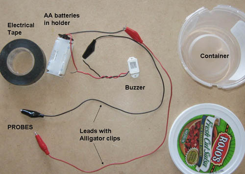
Figure 1. The partially assembled circuit tester. The connections have not been wrapped with electrical tape yet. The tester will buzz if current can flow between the two probes. The probes can be stored in the container when not in use.
Setting Up the Circuit
- Strip about 2 cm of insulation from the end of the battery pack's red wire. If you have never used wire strippers before, ask an adult for help or see the video at the bottom of the Science Buddies Wire Stripping Tutorial page.
- Strip about 2 cm from the end of the red wire from the buzzer.
- Twist the ends of the red wires together from the battery pack and the buzzer. Important: pay attention to the wire colors! If you twist the battery pack's red wire to the buzzer's black wire, the buzzer will not work at all. Make sure you twist the battery pack's red wire to the buzzer's red wire.
- Wrap electrical tape around the exposed twisted red wires.
- Attach a black alligator clip to the black wire from the buzzer.
- Wrap electrical tape around the black alligator clip and the black wire from the buzzer.
- Even though the alligator clip is insulated, there is a chance the bare wire might touch another bare wire. The electrical tape ensures the bare wire is insulated.
- Attach a red alligator clip to the black wire from the battery pack.
- Wrap electrical tape around the red alligator clip and the black wire from the battery holder to insulate the bare wire.
- Put the two AA batteries into the AA battery pack. Important: Make sure that the "+" symbols on the batteries line up with the "+" symbols inside the battery pack.
- Touch the red and the black probes together. You should hear a buzz from the buzzer. If you don't, check the batteries and your connections and try again. See Figure 2.
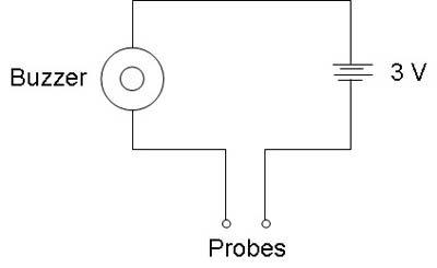
Figure 2. Diagram for the circuit tester. When the two probes are connected to a conductor, current flows through the circuit, activating the buzzer.
Housing the Tester
- Thoroughly clean and dry a 16-oz. plastic container and its snap-on top.
- Figures 1 and 3 show a salsa container. You can use whatever type of container you choose.
- Use the scissors to cut two notches in the top rim of the base of the plastic container. Refer back to Figure 1, above. Have an adult help you with this step.
- Place the buzzer, the battery pack and the wires inside the plastic base.
- Rest the wire for the red probe in one of the notches, so that the probe is on the outside of the container.
- Rest the wire for the black probe in the other notch, so that the probe is on the outside of the container.
- Punch five holes in the lid, using the hole punch or a screwdriver. This will make it easier to hear the buzzer.
- Place the lid on top of the container.
Testing the Flow of Electricity
Important Note: The circuit tester can be used to determine whether two things are electrically connected to each other. If two things are electrically connected, current can flow between them. The tester will buzz if current can flow between the two probes. Caution: Make sure anything you choose to test is not plugged into a wall socket or powered by batteries.
- Check to make sure an incandescent lightbulb is in the lamp.
- Plug the lamp in and turn it on to test that the light bulb works. If it does not light, replace the lightbulb with a new incandescent light bulb.
- Turn the lamp off.
- Unplug the lamp.
- Attach one probe to each prong of the plug. See Figure 3.
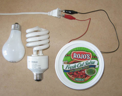
Figure 3. Circuit tester attached to lamp plug. The two kinds of lightbulbs are shown: incandescent bulb (left) and energy-saving fluorescent bulb (right).
- Does the buzzer make a noise? Record your observations in your lab notebook in a data table, like the one below.
| Lamp (Unplugged) | ||
| Light bulb | Switch | Buzzer (On/Off) |
| Incandescent | On | |
| Incandescent | Off | |
| Fluorescent | On | |
| Fluorescent | Off | |
- Turn the lamp switch ON. Note: The lamp should remain unplugged at all times.
- Does the buzzer make a noise now?
- Remove the incandescent light bulb.
- What happened to the circuit when the light bulb was removed?
- Replace the incandescent light bulb with the energy-saving fluorescent light bulb.
- What happens to the buzzer?
- Turn the switch on the lamp OFF.
- What happens to the buzzer now?
- Explain your results.
- Look inside the incandescent light bulb. Do you see why there is a circuit?
- For the energy-saving light bulb, how would you explain your results? Hint: What is needed in this kind of lightbulb to make electricity flow?
- Repeat steps 1–15 with two different lamps.
Have you ever thought about adding a little bit more than just your articles? I mean, what you say is important and all. But think of if you added some great pictures or videos to give your posts more, “pop”! Your content is excellent but with pics and videos, this site could undeniably be one of the best in its field. Wonderful blog
ReplyDeletehomemade wire stripper
Thanks for posting this info. I just want to let you know that I just check out your site and I find it very interesting and informative. I can't wait to read lots of your posts. פאנלים סולאריים לבית
ReplyDeleteThis is such an insightful post! Your analogy of electricity flowing like water makes it so much easier to understand circuits. Speaking of testing electrical flow, have you tried using a Fluke tester? It's a reliable tool, especially popular here in the Philippines, for checking if electricity can flow between two objects. Thanks for sharing these valuable tips on homemade electronic testing!
ReplyDeleteThis post really simplifies how electricity flows comparing it to water makes it so easy to understand! When I test circuits at home, I always rely on my Fluke 87V Max True-RMS Digital Multimeter because it’s super accurate and tough enough for any project. It’s amazing how a reliable tool can make checking for current flow so much safer and straightforward.
ReplyDelete