Tuesday 28 July 2015

Paper Circuit

Introduction

Have you ever made a painting or drawing that included lights, like light from the sun, or from the windows of a house at night? Do you think it would be fun if those light sources could actually light up? That is what paper circuits allow you to do—build real lights directly into your drawings or paintings, like the one in Figure 1.
paper circuit LED flowers

Figure 1. An example of a paper circuit that includes real lights in the centers of the flowers.An electrical circuit is a loop where electricity can flow. A basic circuit requires a battery, which stores electricity (other types of circuits can get electricity from other places, like a wall outlet). The battery must be connected to a light with materials that let electricity flow easily (kind of like water flowing easily through a pipe). These materials are called conductors (materials that do not let electricity flow easily are called insulators). Figure 2 shows a diagram of a basic circuit.
A diagram of a basic circuit.
Figure 2. A diagram of a basic circuit. Electricity is supplied by the battery. It flows in a loop through the conductor (which, in this figure, is a wire), to the light, and then back to the battery.
Conductors for most circuits (like the wires for the lights in your house, or inside a computer) are made out of copper wire, because copper is a very good conductor. However, there are many different options for conductive materials in paper circuits, as shown in Figure 3.

Conductors used in paper circuits

Figure 3. The conductive materials you might test in this project. From top to bottom: artist's graphite pencil, #2 pencil, conductive ink, electric paint, copper tape, and aluminum foil.

There are also different types of batteries, as shown in Figure 4. You might be familiar with AA or AAA batteries, commonly used in toys and electronic devices.Coin cell batteries—the type found in watches—are tiny, flat, and lightweight. 9 volt batteries are bigger and heavier, but have a higher voltage, which is how hard the battery "pushes" on the electricity (the coin cell batteries in this project are only 3 volts [V]). A higher voltage can "push" electricity through a less conductive material, whereas a low voltage requires a very conductive material in order to push a lot of electricity through.
9 volt and coin cell battery

Figure 4. A 9 V battery (left) and a coin cell battery (right). In this project, you will test each of the conductive materials shown in Figure 3 with the batteries in Figure 4, to light up a tiny light called an LED (which stands for light-emitting diode). Which materials do you think will work with which battery? What combination do you think will be the "best" overall for an art project? Read the Questions and Bibliography sections to get started making your hypothesis.

Terms and Concepts

  • Circuit
  • Conductor
  • Insulator
  • Battery
  • Coin cell battery
  • 9 volt (V) battery
  • Voltage
  • Light-emitting diode (LED)

Questions

  • What are some different materials that can be used as conductors in paper circuits?
  • What are some examples of paper circuit projects? Hint: Do an internet search for "paper circuit" and look at some of the projects that come up.
  • Look closely at the example paper circuit projects you find.
    • What type of conductive material do they use?
    • What type of battery do they use?
  • Do a search to see what types of materials usually make "good" conductors, and what types are poor conductors.

Materials and Equipment

The following materials are available from SparkFun Electronics:
  • 5 mm copper tape, SparkFun Electronics part # PRT-10561
  • Electric paint pen, SparkFun Electronics part # COM-11521
  • Conductive ink pen, SparkFun Electronics part # COM-13254
  • 9 volt battery, SparkFun Electronics part # PRT-10218
  • 2032 coin cell battery, SparkFun Electronics part # PRT-00338
  • Alligator clip test leads, SparkFun Electronics part # PRT-12978
    • Note: These are sold as a 10-pack, but you only need 2 for this project.
  • Pack of assorted LEDs, SparkFun Electronics part # COM-12062
    • Note: You only need a few LEDs for this project, but you can use additional ones for your artwork.
The following materials are available from home or an art supply store:
  • Artist's graphite pencil(s) and/or #2 pencils, an art supply store.
    • Note: Pencils are labeled with letters and numbers that indicate a hardness scale. For example, #2 pencils might also have the letters "HB" on them. The pack of graphite pencils listed above contains 2B, 4B, and 6B pencils. To learn more about the pencil hardness scale, If you buy multiple pencils with different hardness ratings, you can test all of them.
  • Aluminum foil
  • Printer paper or construction paper (at least 6 sheets)
  • Scotch® tape
  • Metric ruler
  • Scissors
  • Thin paintbrush
  • Drawing or painting materials of your choice (markers, colored pencils, crayons, etcetera)
  • Newspaper to protect your work surface
  • Lab notebook

Thursday 16 July 2015

Use a homemade electronic tester to find out if electricity can flow between two objects.

Introduction

Electricity is like water in a river, it flows. For example, when you turn on a lamp, electricity flows in through the power cord, then it flows through the lightbulb, and finally, it flows back out through the power cord. Electricity flows through conductors. Most metals are good conductors. Copper is an excellent conductor, so it is used in power cords. To keep the electricity from flowing where it is not supposed to go, conductors that carry electricity are surrounded by insulators. Plastic and rubber are good insulators, which is why they are used to coat power cords. If electricity is like water flowing down a river, the conductors are like the sides of the river—they keep it within certain areas. 
Electricity has to flow into and out of an object to provide power, and the path of the electricity is called a circuit. A circuit is a circular journey. In an electrical circuit, the electricity makes a circular journey through the device it is powering. For example, when a lamp is turned on, a circuit is formed from the socket in the wall, through the lamp, and then back to the socket. If the path of the electricity is broken, then the flow of electricity is stopped and the power to the device is turned off. The role of switches is to break the flow of electricity. A common type of switch has two pieces of metal that touch to make a circuit, and separate to break the circuit. More complex switches are used in electronic devices, but the basic idea is the same, they interrupt the flow of electricity.
You can test whether two objects are connected in a circuit using a device called a circuit tester (also called a continuity tester). In this electronics science fair project, you will make your own circuit tester. To determine if there is a path for electricity through a lamp, you will unplug it and attach probes to the prongs of the plug. When it is plugged in, electricity flows into the lamp from one prong and out through the other prong. By attaching your circuit tester to the two prongs, you can determine if there is a closed circuit for the flow of electricity. You will also determine how the lamp switch and the type of lightbulb affect the flow of electrical current.

Terms and Concepts

  • Conductor
  • Insulator
  • Circuit
  • Switch
  • Circuit tester
  • Continuity tester
  • Closed circuit
  • Current
  • Circuit diagram
  • Alternating current

Questions

  • What word is used by scientists to describe the flow of electricity? Hint: Think of the word for "moving water."
  • How many types of switches can you find in your house?
  • What is the definition of an open circuit?
  • What is voltage?
  • How are current and voltage related?
  • What are some examples of good conductors and good insulators?

Materials and Equipment

Experimental Procedure

Note Before Beginning: This science fair project requires you to hook up one or more devices in an electrical circuit. Basic help can be found in the Electronics Primer. However, if you do not have experience in putting together electrical circuits you may find it helpful to have someone who can answer questions and help you troubleshoot if your project is not working. A science teacher or parent may be a good resource. If you need to find another mentor, try asking a local electrician, electrical engineer, or person whose hobbies involve building things like model airplanes, trains, or cars. You may also need to work your way up to this project by starting with an electronics project that has a lower level of difficulty.
Important Safety Notes Before You Begin:
  • All devices that are tested should be disconnected from a power source.
  • Don't take any electrical appliances apart to test components inside.
  • Do not go near the sockets in the wall with the circuit tester.

Continuity tester.
Figure 1. The partially assembled circuit tester. The connections have not been wrapped with electrical tape yet. The tester will buzz if current can flow between the two probes. The probes can be stored in the container when not in use.

Setting Up the Circuit

  1. Strip about 2 cm of insulation from the end of the battery pack's red wire. If you have never used wire strippers before, ask an adult for help or see the video at the bottom of the Science Buddies Wire Stripping Tutorial page.
  2. Strip about 2 cm from the end of the red wire from the buzzer.
  3. Twist the ends of the red wires together from the battery pack and the buzzer. Important: pay attention to the wire colors! If you twist the battery pack's red wire to the buzzer's black wire, the buzzer will not work at all. Make sure you twist the battery pack's red wire to the buzzer's red wire.
  4. Wrap electrical tape around the exposed twisted red wires.
  5. Attach a black alligator clip to the black wire from the buzzer.
  6. Wrap electrical tape around the black alligator clip and the black wire from the buzzer.
    1. Even though the alligator clip is insulated, there is a chance the bare wire might touch another bare wire. The electrical tape ensures the bare wire is insulated.
  7. Attach a red alligator clip to the black wire from the battery pack.
    1. Wrap electrical tape around the red alligator clip and the black wire from the battery holder to insulate the bare wire.
  8. Put the two AA batteries into the AA battery pack. Important: Make sure that the "+" symbols on the batteries line up with the "+" symbols inside the battery pack.
  9. Touch the red and the black probes together. You should hear a buzz from the buzzer. If you don't, check the batteries and your connections and try again. See Figure 2.

Continuity tester.
Figure 2. Diagram for the circuit tester. When the two probes are connected to a conductor, current flows through the circuit, activating the buzzer.

Housing the Tester

  1. Thoroughly clean and dry a 16-oz. plastic container and its snap-on top.
    1. Figures 1 and 3 show a salsa container. You can use whatever type of container you choose.
  2. Use the scissors to cut two notches in the top rim of the base of the plastic container. Refer back to Figure 1, above. Have an adult help you with this step.
  3. Place the buzzer, the battery pack and the wires inside the plastic base.
  4. Rest the wire for the red probe in one of the notches, so that the probe is on the outside of the container.
  5. Rest the wire for the black probe in the other notch, so that the probe is on the outside of the container.
  6. Punch five holes in the lid, using the hole punch or a screwdriver. This will make it easier to hear the buzzer.
  7. Place the lid on top of the container.

Testing the Flow of Electricity

Important Note: The circuit tester can be used to determine whether two things are electrically connected to each other. If two things are electrically connected, current can flow between them. The tester will buzz if current can flow between the two probes. Caution: Make sure anything you choose to test is not plugged into a wall socket or powered by batteries.
  1. Check to make sure an incandescent lightbulb is in the lamp.
  2. Plug the lamp in and turn it on to test that the light bulb works. If it does not light, replace the lightbulb with a new incandescent light bulb.
  3. Turn the lamp off.
  4. Unplug the lamp.
  5. Attach one probe to each prong of the plug. See Figure 3.


Continuity tester.
Figure 3. Circuit tester attached to lamp plug. The two kinds of lightbulbs are shown: incandescent bulb (left) and energy-saving fluorescent bulb (right).
  1. Does the buzzer make a noise? Record your observations in your lab notebook in a data table, like the one below.

Lamp (Unplugged)
Light bulbSwitchBuzzer (On/Off)
IncandescentOn 
IncandescentOff 
FluorescentOn 
FluorescentOff 

  1. Turn the lamp switch ON. Note: The lamp should remain unplugged at all times.
  2. Does the buzzer make a noise now?
  3. Remove the incandescent light bulb.
  4. What happened to the circuit when the light bulb was removed?
  5. Replace the incandescent light bulb with the energy-saving fluorescent light bulb.
  6. What happens to the buzzer?
  7. Turn the switch on the lamp OFF.
  8. What happens to the buzzer now?
  9. Explain your results.
    1. Look inside the incandescent light bulb. Do you see why there is a circuit?
    2. For the energy-saving light bulb, how would you explain your results? Hint: What is needed in this kind of lightbulb to make electricity flow?
  10. Repeat steps 1–15 with two different lamps.

Saturday 4 July 2015

How Well Do Different Materials Create Static Electricity

Introduction

Static electricity is the build-up of electrical charge in an object. Sometimes static electricity can suddenly discharge, like when a bolt of lightning flashes through the sky. Other times, static electricity can cause objects to cling to each other, like socks fresh out of the dryer. The static cling is an attraction between two objects with different electrical charges, positive (+) and negative (-). 
You can create static electricity by rubbing one object against another object. This is because the rubbing releases negative charges, called electrons. The electrons can build up to produce a static charge. For example, when you shuffle your feet across a carpet you are creating many surface contacts between your feet and the carpet, allowing electrons to transfer to you you, building up a static charge on your skin. You can suddenly discharge the static charge as a shock when you touch a friend or some objects. Similarly, when you rub a balloon on your head it causes opposite static charges to build up in your hair and in the balloon. When you pull the balloon slowly away from your head, as shown in Figure 1, below, you can see these two static charges attracting each other - your hair stands on end, and tries to stick to the balloon!
Girl with static hair and balloon
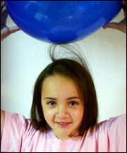
Figure 1. Static electricity makes your hair stand up! (NASA, 2004)
How can static electricity be measured? One way is to use an electroscope. An electroscope is a scientific instrument that detects if there is an electrical charge, and it can show how big the electrical charge is. A drawing of one type of electroscope is shown in Figure 2, below. How does it work? An electrical charge is transferred to the electroscope (by touching it, as shown with the dark green rod), and the electrical charge goes into two separate metal pieces on the electroscope. In the drawing below, these two pieces are in yellow, and represent two thin pieces of gold. The electrical charge makes both of these pieces have the same charge. While objects that have opposite charges are attracted to each other (like the balloon and your hair), objects that have the same charge (such as in the electroscope) are actually repelled by, or pushed away from, each other. In the electroscope drawing, the two pieces of gold have become charged with the same charge (they are either both negatively charged, or both positively charged), so they are pushed apart from each other. The bigger the charge, the further apart the two pieces are pushed. If the gold pieces have no charge (in other words, they are neutral), or they have opposite charges, then they will hang straight down, touching each other.
Diagram of an electroscope.
Figure 2. This is a drawing of a simple electroscope. When the electroscope receives an electrical charge (from the green rod at the top), the two gold pieces (in yellow) push apart from each other. The bigger the charge the electroscope receives, the further apart the gold pieces are pushed. If the gold pieces have no electrical charge, they will hang straight down, touching each other. (Image credit: User Stw)
In this science project you will build a homemade electroscope to test several objects made out of different materials to see which ones produce, or conduct, the most static electricity. Then you will put your results together to formulate a triboelectric series, which is an ordered list that describes the type of charge an object has as a result of static electricity. The results may shock you!

Terms and Concepts

  • Static electricity
  • Electrical charge
  • Electrons
  • Electroscope
  • Neutral
  • Triboelectric series

Questions

  • How can static electricity be measured?
  • How do different materials react to static electricity?
  • Which materials are neutral and which ones are charged?
  • How does an electroscope work?

Bibliography

This idea was adapted from a project on how to build an electroscope on the ZOOM science activities website hosted by PBS Kids:
  • PBS Kids. (n.d.). Science Rocks! Electroscope. ZOOM, WGBH Educational Foundation, Boston, MA. Retrieved March 28, 2006, from

Materials and Equipment

  • Styrofoam™ cup
  • Sharp pencil or skewer
  • Plastic drinking straw
  • Aluminum pie pan
  • Tape
  • Optional: Clay
  • Scissors
  • Thread
  • Aluminum foil
  • Styrofoam plate. Alternatively, the Styrofoam lid from a take-out food container would work too.
  • Balloon
  • A desk or table that is not metal. For example, a wooden, plastic, or glass desk or table would work. This is because these materials do not conduct electricity as well as metal does.
  • Wooden ruler, metric
  • Different materials to test (at least 3). They should be no larger than the plate, or be able to be folded to be this small, and be able to be laid flat. Small samples of different fabrics are usually available at stores that sell fabric. For example, you could pick at least three of the following materials:
    • Polyester
    • Nylon
    • Cotton
    • Wool
    • Silk
    • Aluminum
    • Plastic wrap
    • Plastic, such as a flat, plastic comb
    • Copper
    • Wood
    • Tissue paper
  • Lab notebook

Experimental Procedure

  1. First you will make an electroscope to test for the presence of static electricity in different materials. Your electroscope will look different from the one in Figure 2 in the Introduction, but it will work the same way. Instead of using two gold pieces, your electroscope will use an aluminum pan and an aluminum ball on a string. When it is finished, your electroscope will look like the one in Figure 6. We will explain more about how this design works in a moment. Here is how to make the electroscope:
    1. Make two holes near the bottom of a Styrofoam cup on opposite sides. A good way to do this is by pushing a sharp pencil or skewer through the cup.
    2. Push a plastic straw through both of the holes in the cup so that your setup now looks like Figure 3.

      A straw in the bottom of a Styrofoam cup, the first step of making an electroscope
      Figure 3. After making a two holes in the cup, push a plastic straw through both of them.
    3. Either securely tape the cup's opening to the aluminum pan, as shown in Figure 4, or use clay to hold the cup to the pan. If you are using clay, stick four little balls of clay (each about 2 centimeters [cm] in diameter) to the rim of the cup, then turn the cup upside down and stick it to the bottom of the aluminum pie pan using the clay.
    4. Carefully adjust the straw's position so that one end of the straw is right above the edge of the pan, as shown in Figure 4.

      A cup (with a straw through it) taped to an aluminum pan.
      Figure 4. Secure the cup's top to the aluminum pan by either using tape, as shown here, or small balls of clay. Carefully move the straw so that one end is right above the pan's edge.
    5. Cut a piece of thread with a length that is about two or three times the distance between the straw and the pan's edge. Tie a few knots in one end of the thread.
    6. Cut a square of aluminum foil that is about 3 cm on each side. Use it to make a ball around the knots in the thread, as shown in Figure 5. The ball should be about the size of a marble or a little smaller. It should be just tight enough so it does not fall off the thread.

      A piece of thread with a small ball of aluminum foil on one end.
      Figure 5. Make a small ball of aluminum foil fit securely over the knots on the end of the piece of thread.
    7. Tape the thread to the tip of the straw so that the ball of foil hangs straight down from the straw, just touching the edge of the pan, as shown in Figure 6. Adjust the straw's position if needed. If the end of the thread without the ball is dangling down and touching the pan, cut the dangling part off so it does not touch the pan.

      A homemade electroscope.
      Figure 6. When you are finished, your electroscope should look similar to this one. Make sure the ball of aluminum foil is touching the edge of the aluminum foil pan.
    8. If the straw seems loose at all, tape the straw to the cup (or wedge in some clay) so the straw does not move around when you use the electroscope.
  2. To test the electroscope, create some static electricity by rubbing a blown-up balloon on a Styrofoam plate or the Styrofoam lid from a take-out food box. Rub the Styrofoam plate about 20 times with the balloon.
    1. When you rub the balloon on the Styrofoam plate, the plate gets an electrical charge, which means there is a buildup of electrons (on either object, the balloon or the plate). Even though the plate is charged, the electrons stay where they are because Styrofoam does not conduct electricity.
  3. Once you have charged the Styrofoam plate, quickly place the plate on a desk or table (make sure not to use a metal surface). Then place the electroscope on top of the Styrofoam plate. Be sure to only hold the electroscope by the foam cup and not the aluminum pan, otherwise it will not work! You should see the aluminum foil ball move away from the edge of the pan, as shown in Figure 7.
    1. What is happening? When an object, like the Styrofoam plate, gets an electrical charge, it can be either positive or negative. (If an object has a lot of electrons, it can have a negative charge, but if it does not have many electrons, it can have a positive charge. Whether an object tends to gain or loses electrons depends on the type of material it is made out of.) When a charged object (like the charged plate) touches the aluminum pan, the charge (or electrons) easily moves through the metal pan. Since the aluminum ball is touching the pan, the ball gets the same charge as the pan. This means that both the ball and pan have the same charge (they are either both positively or negatively charged). Because objects that have the same charge are repelled by each other, the ball is pushed away from the pan.
    2. If you are unsure of how this works, re-read the Introduction in the Background section.
A homemade electroscope on a styrofoam lid.
Figure 7. After putting the electroscope on the charged Styrofoam plate, the aluminum ball should move away from the aluminum pan, as shown here.
  1. Use a wooden ruler to measure the distance between the foil ball and the pan. The more charge there is, the more distance there will be. Be careful not to touch the ball or the edge of the plate with the ruler (or your body) when you measure this distance. In your lab notebook, make a data table like Table 1, and record your results in it. (This will be Trial 1 using Styrofoam.) In your data table, only list the objects you actually test.
  2. Now, touch the ball with your finger. What happens? Record any observations in the data table in your lab notebook.
ObjectType of MaterialTrial NumberDistance Between Ball and Pan (cm)Average Distance Between Ball and Pan (cm)Observations
Styrofoam plateStyrofoam1   
2 
3 
Wool hatWool1   
2 
3 
Tissue paperTissue1   
2 
3 
Piece of cotton fabricCotton1   
2 
3 
Table 1. In your lab notebook, make a data table like this one to record your results in. In this data table there are some objects listed as examples, but in your own data table only include the objects you actually test.
  1. Now that you know your electroscope works, you will use it to test the static electricity present in different materials. See the Materials section for a list of different materials to try. You will want to try at least three different types of materials. To test a material, do the following:
    1. Discharge your electroscope by touching the pan with your finger.
    2. Rub the object you want to test about 20 times with the balloon.
    3. Once you have charged the object, quickly lift up the electroscope (holding it by its Styrofoam cup) and place the object on top of the Styrofoam plate so that the object is laying flat on the plate. Make sure the object is not touching the table. Then place the electroscope on top of the object, as shown in Figure 8.
      1. Note: Putting the object on top of the Styrofoam plate will help prevent the electric charge from leaving the object before it can go into the electroscope.
    4. Use the wooden ruler to measure the distance between the foil ball and the pan, making sure not to touch the pan or ball with your ruler (or your body). Record your results in your data table. Then touch the ball with your finger and record your observations.
    5. Repeat steps 6.a. to 6.d. two more times for the same object so that you have done three trials using the same material.
    6. Repeat steps 6.a. to 6.e. for each object you want to test. Be sure to do two more trials using the Styrofoam plate (as you did in steps 2 to 5) so that you have done three trials with it. When you are done, you should have done a total of three trials with each object/material.
A homemade electroscope on pink tissue paper.
Figure 8. To test a charged object, lay it flat in between the electroscope and the Styrofoam plate, as shown here using pink tissue paper.
  1. Once you are done testing, for each object calculate the average distance between the ball and the pan for the three trials. Record your results in your data table.
    1. For example, if when testing the Styrofoam plate you measured the distance to be about 0.5 cm in trial 1, 0.75 cm in trial 2, and 0.5 cm in trial 3, the average distance would be about 0.6 cm (since 0.5 cm + 0.75 cm + 0.5 cm equals 1.75 cm, and when divided by three this equals 0.6 cm).
  2. Make a bar graph of your results.
    1. On the x-axis (the horizontal axis) put the material that was tested, and on the y-axis (the vertical axis) put the average distance between the ball and the pan. Make a bar for each material you tested.
    2. You can make a graph by hand or by using a computer program such as Create a Graph.
  3. Analyze your results.
    1. Which materials were the most electrically charged (had the largest distance between the ball and plate) and which were the least charged?
    2. Arrange the materials from most charged to least charged. This is a Triboelectric series, and can be written as an ordered list or chart. How do common objects rank in the series? You can do some additional research on Triboelectric series, such as by looking at the resources in the Bibliography, and see how your results compare to other established series. What are some similarities, and what are some differences?